

The retaining wall seen in the photograph was originally built over one hundred years ago – possibly much longer, and is a main feature in the centre of a small Sussex village. For many years, the wall was known to be leaning outwards, until one November 5th, it collapsed during the late evening. The owners of the property thought it was a firework exploding, and did not investigate until the following morning, when they were advised that their wall was blocking the road.
I live in the village, and the owners know that I have built a lot of walls locally, and by eight a.m. my small team was busy, clearing the road and sorting through the debris. (This project is the subject of an article in The Library titled The Complete Quote. This document shows how the project was approached and a CDM Plan was formulated to provide the customers and myself full protection for the many legal aspects of working on such commissions).
The length of the collapsed wall was approximately ten linear metres, although from the amount of debris, and the scale of the works it appeared more than the actual measurements. The height of the wall was approximately 150 cm. Because the damaged wall was only one section, with existing walls both left and right still stable and seemingly unaffected by the collapse, I called in a Structural Engineer for advice (any retaining wall over 600mm must be designed and specified by a qualified S.E) I did not require a plan as such, as I was obliged to tie in both of the existing walls. Therefore, a standard form of constructing a concrete block wall, in hollow concrete blocks filled with reinforced concrete would not be suitable for this particular site. The solution had to be to rebuild the retaining wall whilst at the same time, securing, or ‘locking in’ the existing walls as far as possible.
Having excavated the foundations (previously non-existent, which was not surprising due to the age of the wall) to a depth of 600mm, coincidently down to bedrock, and 900mm wide with five 20mm steel reinforcing bars set into the concrete footings, additional 20mm steel bars were inserted @ 750mm centres into the foundations, set back 125mm from the face of the finished wall. These bars were reinforced with woven bars, again 20mm to form a ‘basket’ weave internal steel wall.
To the rear of the collapsed bank was a rock ‘wall’ comprising plates of solid chalk and stone, so the sideways pressure on the wall was not excessive (the previous existing wall was only stone backed with and held together with mortar, and no additional strength. The collapse was caused by beech hedge roots and trunks rocking in the wind) as the amount of loose material or soil was fairly limited.
Because it was not possible to construct the wall using standard 220mm wide hollow concrete blocks, these were substituted for 100mm solid blocks to the rear, 150mm stonework to the face, with the infill gap of approximately 150mm of wet mix concrete backing the walling stone and encapsulating the steel bars, giving a total wall thickness of 520mm. To the rear of the solid concrete blocks, another single reinforcing bar, also 22mm, was laid along the full length between the block and natural stone ‘wall’ (not shown in the photograph) and backfilled with wet concrete. All concrete used was one part OP cement and four parts sandy ballast. The final thickness of the wall was approximately 750mm along the full ten metre length of the collapsed area. This compared to the original 150mm – 200mm width of the natural stone only.
At either end, as the wall was being built, very wet strong concrete was forced into the stonework at the back of the existing walls, effectively tying them in to the strength of the new build. At the very least, this concrete ‘gripper’ helped to alleviate any pressure on the rear of the existing walls. You will notice in the article The Complete Quote that I heavily underlined the fact that I could not be responsible for any further damage or collapse of the existing walls during construction.
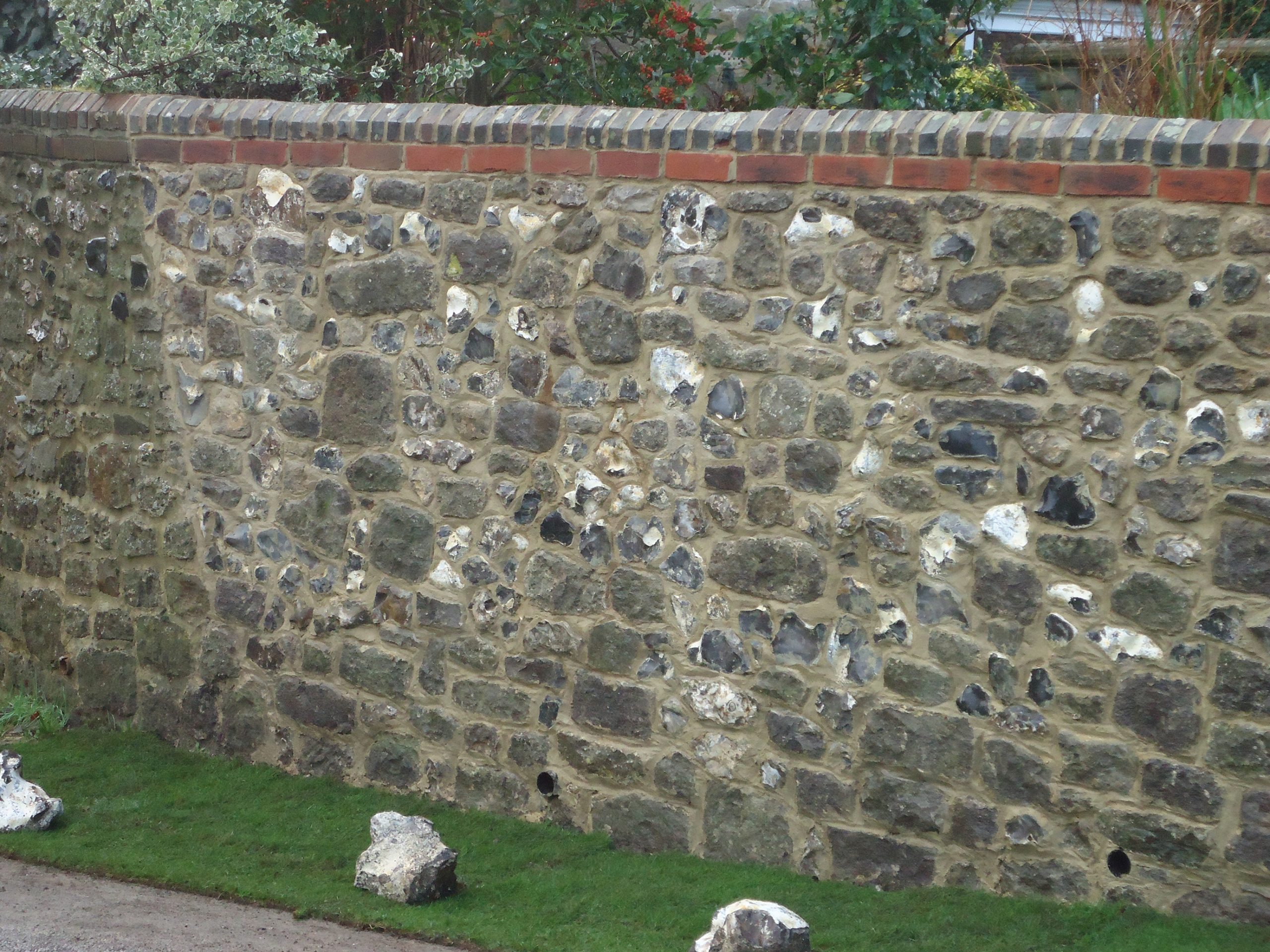
The photograph of the completed wall shows the methods of ensuring that the new works matches the old as far as possible. Copying the same mortar colour and pointing style is a very important part of any restoration work. The choice of material – flint and sandstone in the main – sizes and informal patterns of the wall should blend in such a way that the actual facework is a mirror image of the existing in every detail. The only new product which I was obliged to source was the string line of bricks under the brick header/soldier course. This was because few, if any, of the original bricks were salvageable.
The wall has been in place for six years now, with no sign – not even a hairline crack indicating any movement – between the three sections of wall (old/new/old) and the facework has matured so that the restoration is barely noticeable.
Finally, I have shown a cross sectional drawing of a typical new build retaining wall. Please DO NOT use this as anything other than an example. For all walls over 600mm high you should get a Structural Engineer to either provide you with drawings or a full specification.
Unless you are a qualified and insured professional, even if capable of constructing such walls, you are obliged to engage an Engineer, otherwise if there are any problems or failures in the future, you will be held liable for any costs and damages.

